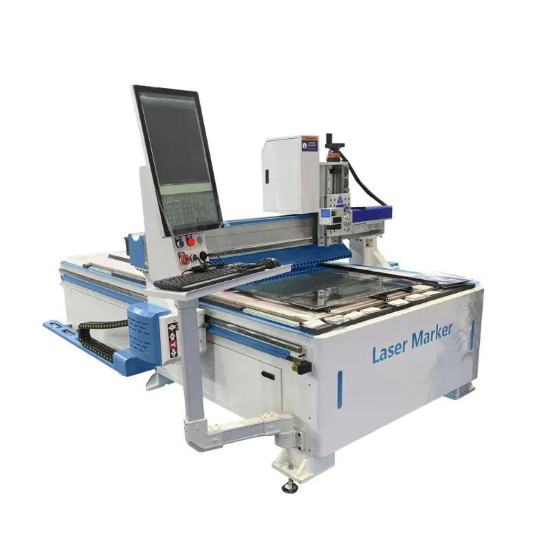
1325 Large Format No Seam Mirror LED Sandblast Marking Engraving Machine JPT Mopa M8 200W Laser Glass Drilling Cutting Machine
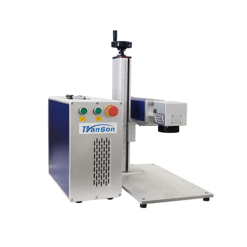
Enclosed Type
Laser engraving machine of circuit connection and the software programming in detail
by:Transon
2020-05-01
1.
Analysis: circuit, explanation, the general idea about the process 1.
1 a lot of I/O port is not used, main is to control the motor and the connection of relay switch is simple it is online to find information of figure 1.
2 with 6560 dial the code switch motor driver module is mainly used to control the size of output current and frequency division ratio.
(
If the X, Y axis motor speed by adjusting the frequency division ratio can reach the effect of the circle)
Motor is not particularly good, the best is lower than the rated current, avoid running time is too long cause motor heating is too big!
!
1.
Three relays and laser circuit connection JP1 is generation refers to the laser head;
JP2 device is refers to the X, Y axis motor 1.
4 laser head part of the circuit.
I was using a 100 mw blue violet laser.
Wood carving enough is enough!
!
!
(
Don't use eyes look directly into the laser)
。
Laser stents are for my own use drawing software, and then with a 3 d printer.
Relay circuit, the principle is to use triode relay to complete switch of the forehead.
5 v relay response time with enough, ordinary relay.
1.
The power is AC - 5
- - - - - -
24 v DC power supply, the output voltage.
Circuit connection part of the basic introduction, carefully follow schematic wiring can be.
2 on software part: use of PC is Grbl Controller software.
The software is a all open source software, its role is mainly to transmit to print model diagram generating nc code to the main control board of laser engraving machine, and you can see in the software printer work (
The location of the laser in the dark, XY axis parameters, the current printing condition, etc. )
And at the same time can be used to manually adjust the parameters under special circumstances.
By upper computer software to control the machine movement.
Burning, burning software use arduino builder to generate good directly.
Hex file can burn to Arduino.
Manually adjust the connection is good after a serial port open GRBL software can be set in the column to the setting, and if the test you carved round isn't too round, adjust the X, Y, every step of the distance is a kind of more effective methods.
2.
1 download GRBL files (
H tt ps: / / dream gi thu division b.
Co gen RBL rb meaning l m/g/g)
The screen shown below, click on the Download ZIP can Download the engineering documents.
After using the compiler (
AVR studio or WinAVR)
Open;
(
I am using AVR studio, Winavr won't configuration hasn't been successful)
Set in the header file.
Header file is part of the code as shown.
Can see the baud rate of transmission, etc. 2.
Part 2 you can see the header files have defined the Arduino and motor of each corresponding relationship between pin ~, after a change to generate a new one.
Hex file (
Using AVR studio)
Then using serial burning software.
Hex file after download directly to the Arduino in specific methods: test the ~ in the pop-up window to send '& gt;
After $G 'feedback data as shown in the burn you, I will.
Hex file ~ 2 effectively.
3 for Grbl can be set directly in the software configuration in the motor parameters without having to modify the long code.
Even don't know anything about the C language for people is also very easy to modify.
As shown in the above, the first three columns for often to modify values, the above is calculated in the motor drive, X, Y axis stepper motor 1 mm per 200 pulse movement, so the value to 195.
Roll back to 195 in order to reduce motor caused by the error so slightly less than the calculated value of 200.
Diagram also listed click acceleration, rolled back and the motor speed, the deviation, the minimum arc and so on.
。
。
。
。
。
Here, circuit and software part also introduces the content of the finished, may encounter with the tutorial in the mismatch problem, actually general train of thought is the same.
Custom message
Related Products