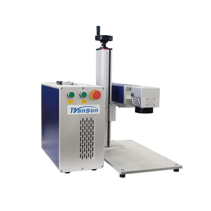
5 In 1 Multifunctional 1500w Handheld Laser Welding Machine Factory Price 5 In 1 Welding Machine with Raycus Max laser source
Enclosed Type
build a cnc router
by:Transon
2020-09-04
Hello, it\'s been a long time since I read instructures, this is my second one.
I don\'t think I will enter all the details, but would love to add them if you need more :-)
However, you will find every plan, STL file, and primary indication of the build machine.
Like every creator I like, I like to create and develop new ideas that help each of us in our daily lives.
I am unable to get into any Workshop, which is why I have started to develop an affordable CNC machine besides my 3D printer, which everyone can easily make with very simple tools.
So I can do what I want!
I didn\'t have a goal when I started: with that in mind, I started drawing some sketches and after a few days I came up with a main idea.
CNC will be closed on the side and it is possible to add a future organic glass cover to the top.
All the electronics are on the back.
Note: some parts that should be 3D printed are aluminum as I have the opportunity to make them during my study internship.
Buy in DIY store: buy on Ebay: Also you need: link to eBay collection as almost every plank is square and I went to DIY store, the small board size is required to be correct.
I made bigger puzzles myself with puzzles, but ordering directly to the DIY store would get better results.
I recommend you to be particularly precise with the x-axis and the wood sticks drilled.
As you can see, some boards have rectangles (long holes).
Their purpose is to adjust the position of the bearing during assembly.
I make them by drilling multiple holes and then using a file, as you can see here: you\'ll find a set of plans bellowI suggests you assemble the x-axis guide rails precisely.
It must be as horizontal as possible, along the track, the distance between the two is equal.
I recommend using 6 to 10 screws between Case_bottom and Case_side.
3 to 4 between Case_side and Case_insideBack/Case_backNote: A schematic diagram of the color inside the shell indicates the height of the guide rail.
There are more screws to come!
I recommend using 6 wood screws between the two axes _ x_main.
6 of each axisa_tprofilalu, 4 of each Axis_side.
First assemble the wood parts, then assemble the aluminum profile.
It\'s not easy for me to be precise. The large bearing near the motor will be used for the timing belt on the x-axis.
When you screw the shaft _ z _ tprofilalu on the shaft _ z _ track, make sure that the screws do not coincide with the surface, otherwise the bearings will come into contact with them.
Install router stand: use 3D printing parts: use router stand, they will be like this :(
Drill holes with 3d printed parts if possible)
Now is the time to put everything together!
Case of X, Y and z axis.
General remarks: first install the x-axis on the z-axis.
Assembled with a 90mm long M5 nut and a threaded rod.
To eliminate inaccuracy, two 3D printed parts must be placed between the two bearings.
They tie together with a zipper.
You will find several versions of it in.
Because the distance between the two bearings ranges from 26mm to 27mm.
Add a z-axis threaded rod with a pulley (
Can be printed in 3D).
The enclosed timing belt is stretched with bearings.
In order to keep it in place, you may have to add a custom 3D printed ring.
Custom 3D printing pulleys on ThingiverseTo install the parts that hold the router (
Actually, it\'s RT0700C)
, Use 3D printing part (
It\'s aluminum here).
Put it into the screw bar and screw it in with M5 hexagonal head.
On the back of the x-axis, I fixed the timing belt with wooden screws.
It may not be the best idea, but it works.
Maybe it would be great to add a washing machine.
This timing belt passes through the Z axis on the bearing and the motor pulley.
The y axis moves the x axis forward from the rear.
That\'s why we set a timing belt between two tracks (as shown above).
Connect the belt about 140 cm first (mesure it! )like that : (
1 each side)
At the front end, the belt rotates a free pulley as shown in the following figure.
Please note that I use the aluminum version and the 3D print version, one on each side.
Fitted with two wooden screws and an M5 screw for the pulley, it looks like this: at the back, there is a system that connects the two belts to a stepping motor through the shaft.
The shaft is the M8 threaded rod, but you can use whatever you want, but it is cheap and can do the job.
It rotates in a 3D printed part, which may affect the tension of the belt.
The first part is fitted with 2 wood screws and 2 M5 screws, which will enable the second part to be connected to it and is just tension.
The wooden screws prevent the M5 screws from rotating as they tighten the plastic.
Then, the second part also installed the bracket of the stepping motor, and now everything should be in place, Let\'s connect everything with the electronics!
Only a few electronic components are needed for the Cnc Machine: I will use GRBL 0.
Here is a sketch of Arduino.
To upload it, just follow the instructions on the website.
It\'s easy.
It just needs to upload a sketch.
Then connect the three step drives to the arduino by tracking these images.
Note: I don\'t know what the switch on the step drive is.
Note 2: once GRBL is on arduino, you have to set it up.
It is important that 1mm in the code correspond to 1mm in reality.
Everything was explained on the website.
Then power the step driver with the power supply.
I also used a plug socket with a circuit breaker.
Arduino will be powered by the computer.
I decided to add some LEDs when the machine was turned on.
It requires a simple Buck voltage converter and a white warm LED strip of 40 cm :-)
Now that the electronics are complete and GRBL is on arduino, our cnc understand that Gcode is a machine language that tells the motor basically when it has to move.
We will set it up using the generic Gcode Sender.
Here\'s how we can do this: then configure GRBL with the help of these instructions.
On the machine control tab, we can move the three Axis to see if it works!
Now let\'s test it with a pen: It looks great!
How does it work with plexiglass?
I used Easel, a free online CAM and CAD software developed by ventables.
It has GRBL support built in and works very well.
Then I try to cut birch and poplar and it looks like this: now that the machine has run a few projects, I can say: point: the improvements brought: I hope you appreciate the project.
Next month (
Since January 2017
I will continue to work hard to improve the design and get better results!
See you next time!
PS: If you have any questions, I would be happy to answer 2018: I would suggest that you do not make the same mistake as I did on custom rails, install straight rails directly on each axis.
On eBay or AliExpress, their prices have fallen sharply and are now very affordable.
It is more difficult, durable and easy to install. Cheers!
Custom message
Related Products