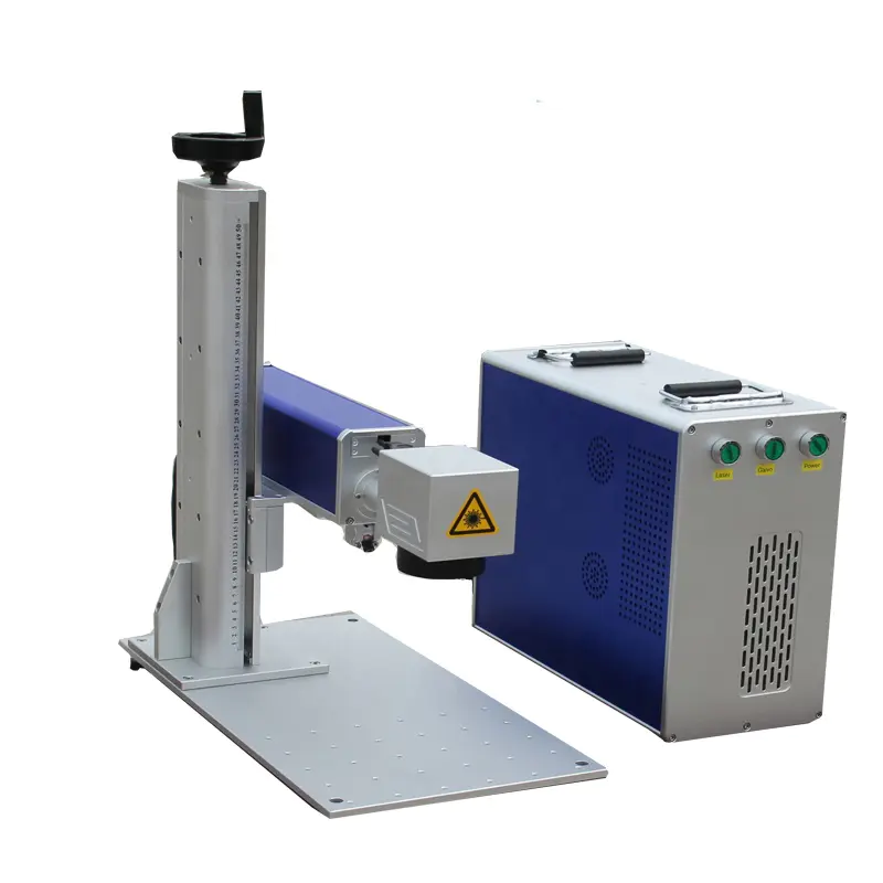
Computer engraving machine mainly includes the axis and Z axis components, X, Y axis parts and worktable for part of the virtual assembly is shown in figure 1.
Figure 1
computer engraving machine machine virtual assembly drawings to calculate maximum principal cutting force Fc, determine the maximum spindle speed Vmax and output torque, selected models for EMP240 dc motor spindle motor, according to the load condition of the X and Y directions, the selected ball screw pair for GD series, at the same time, this article selected according to the load torque stepper motor model for 57 byg4504, choose the corresponding bearing, coupling, guide rail, round nut, design end cover, etc.
axis and Z axis parts: spindle motor, cutting tool installed components, to achieve the main movement of the machine tools and cutting tools under the Z direction carried knives and knife;
X axis parts: installation of stepper motor, bearing the weight of the spindle and the X axis parts and tool in the X axis feed movement;
Y parts: installation of stepper motor, bearing the weight of the Y axis parts, to realize feed movement of cutting tool in the Y direction;
the workbench: install fixture, workpiece was laid.
engraving machine price information in the numerical control network.
We are here to help you! If you close the chatbox, you will automatically receive a response from us via email. Please be sure to leave your contact details so that we can better assist

 E-mail: sales@transoncnc.com
  Mobile: +86 18653117691 (whatsapp)
