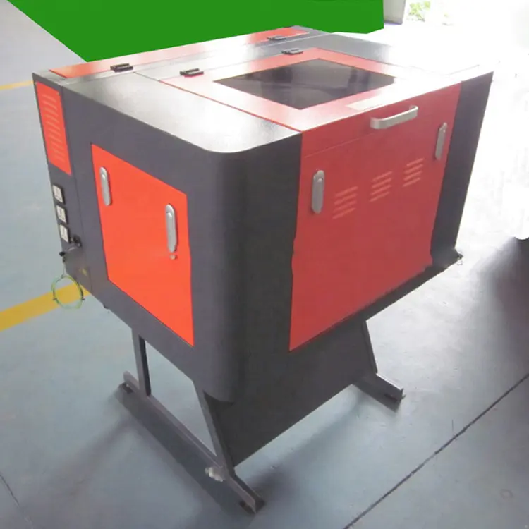
Computer engraving machine based on brushless motor control system software design
by:Transon2020-07-23
Computer engraving machine control system based on brushless motor software process as shown in the figure below.
Using the principle of PWM to control the speed servo motor, servo cycle is 1 ms, implemented by real time interrupt timing.
Sampling pulse TMRCLK hardware implementation accumulative count by DSP, CPU overhead.
Given TMSF240 only three general timer, specific assignment is as follows: T1 time benchmark, as DSP all compare unit for the inverter bridge PWM signal, this feature just set the PWM cycle and duty cycle;
T2 for encoder count, T3 for external clock input (
Directional increase and decrease)
Way.
Because encoder count and external clock count may be great value, so still need additional accumulator variables, in order to save the T2, T3 high words, T2, T3, the high word variable for T2CNTH, T3CNTH, count them as a symbol.
In T2CNT and T3CNT numerical are unsigned number, so high and low words to use at the time of merger & other;
With & throughout;
, i. e. , & other;
T2CNTHlT2CNT”
And & other
T3CNTHIT3CNT”
。
Position feedback parameters of the motor is: 10000 / week, engraving machine price lead: 5 mm/week, so, if a servo cycle received feed increment for the An, the corresponding target position increment (
Encoder line number)
As=(
0. 001报;
An×
10000).
/ 5 = 2报;
The An, because get the position increment with a servo cycle time, so for the servo speed (
In the period of each servo position increment)
。
computer engraving machine control system based on brushless motor software flow chart
We are here to help you! If you close the chatbox, you will automatically receive a response from us via email. Please be sure to leave your contact details so that we can better assist


 E-mail: sales@transoncnc.com
  Mobile: +86 18653117691 (whatsapp)
